Converting dispenser for use in the USA
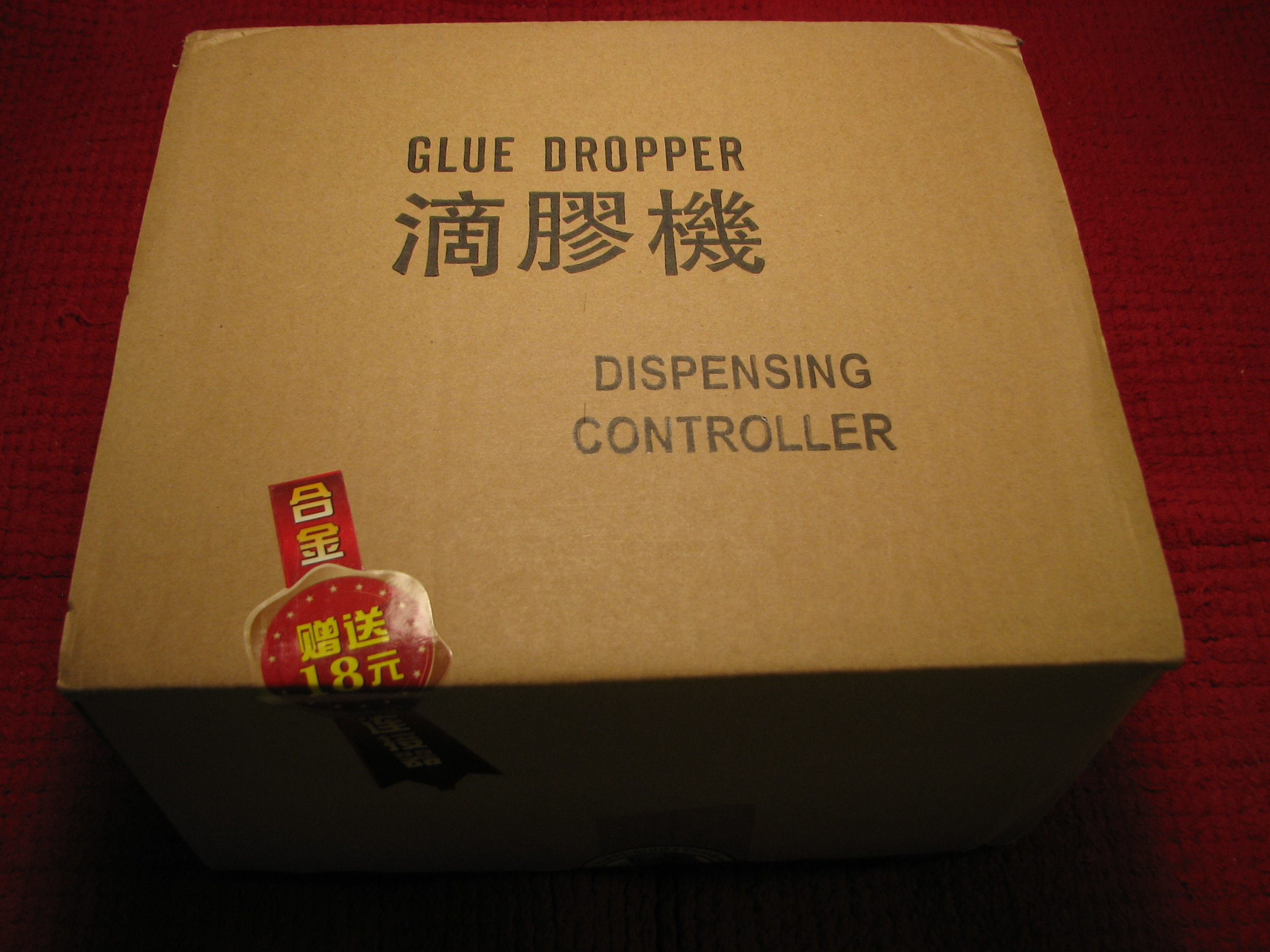
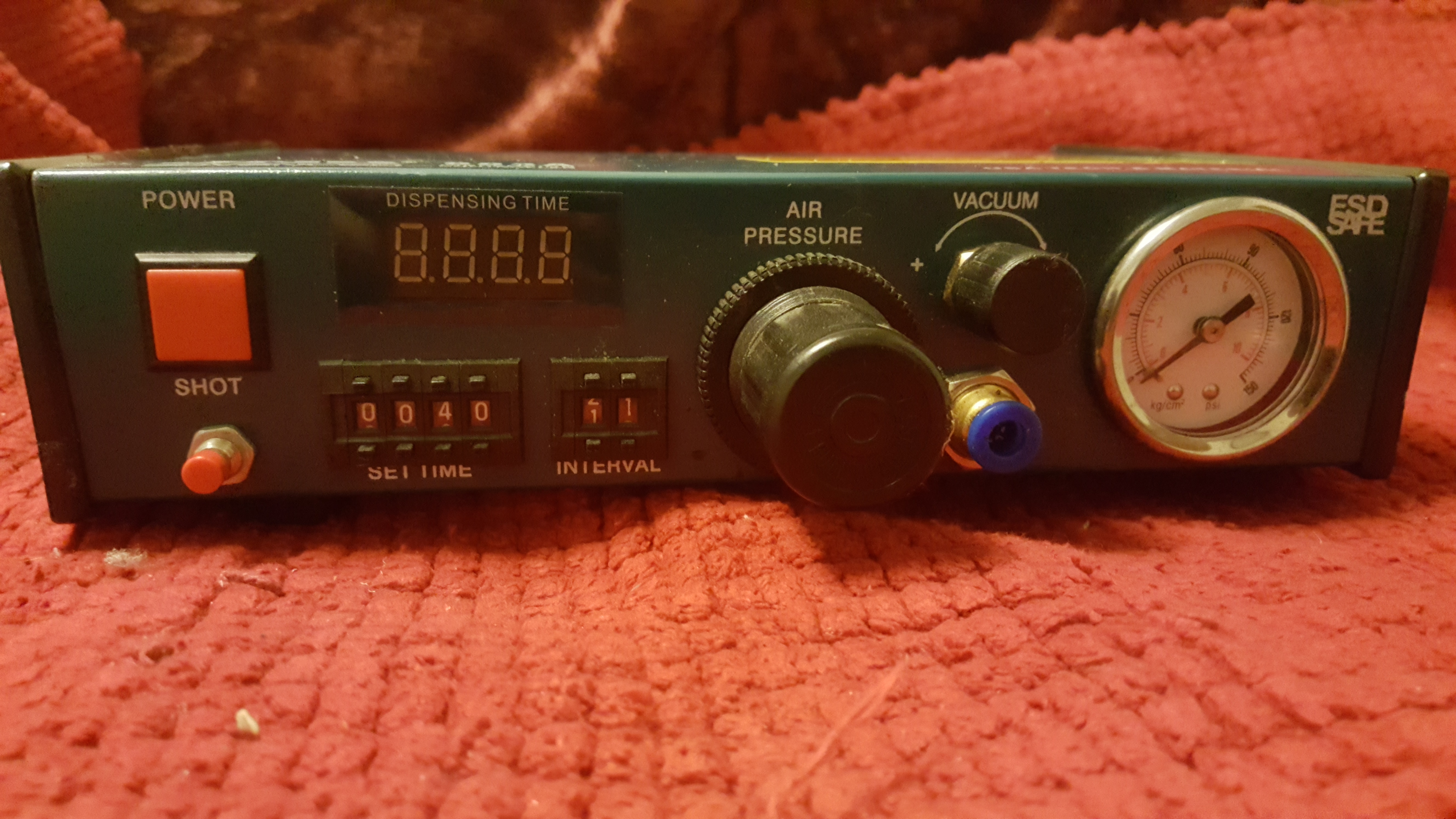
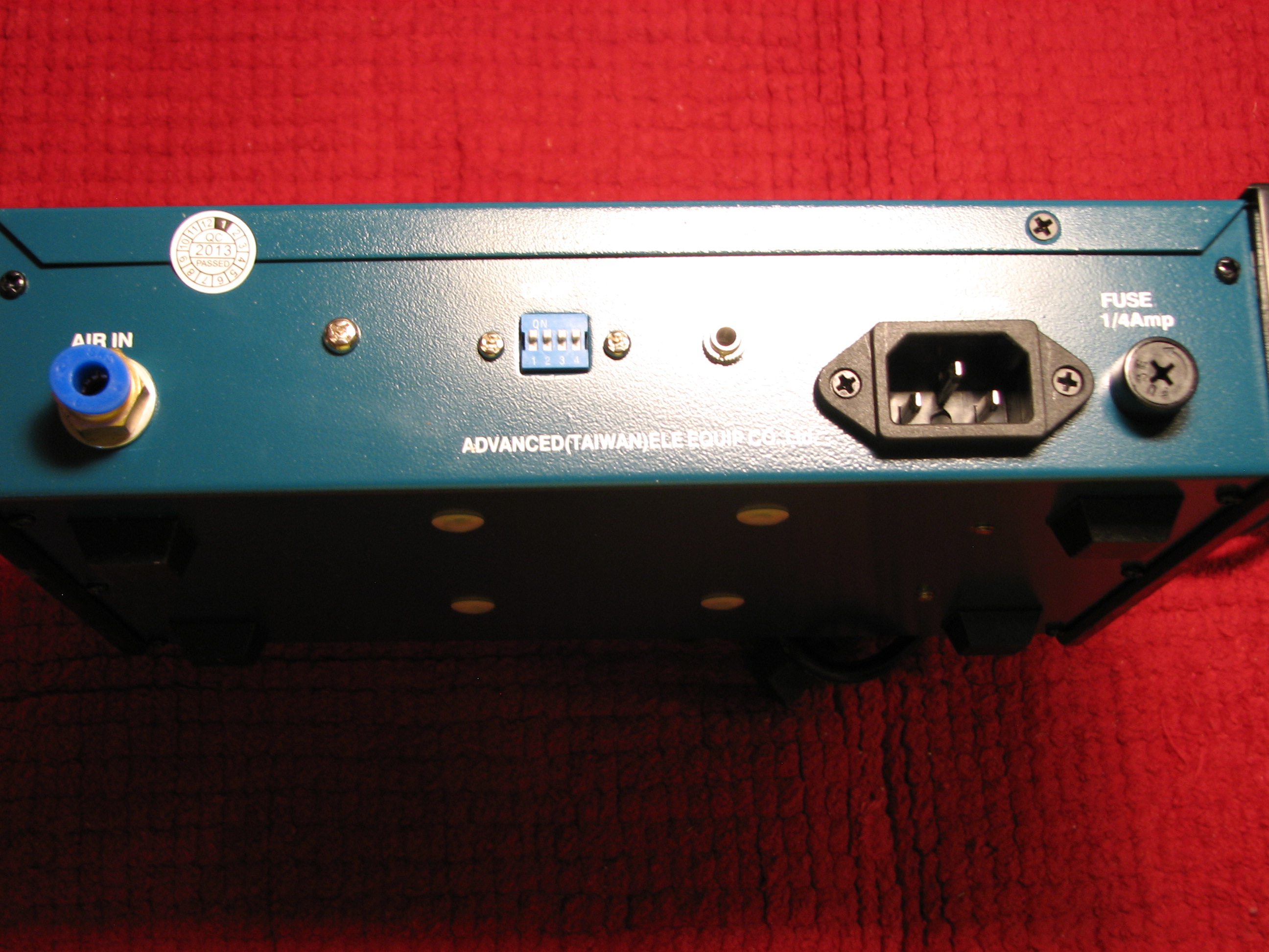
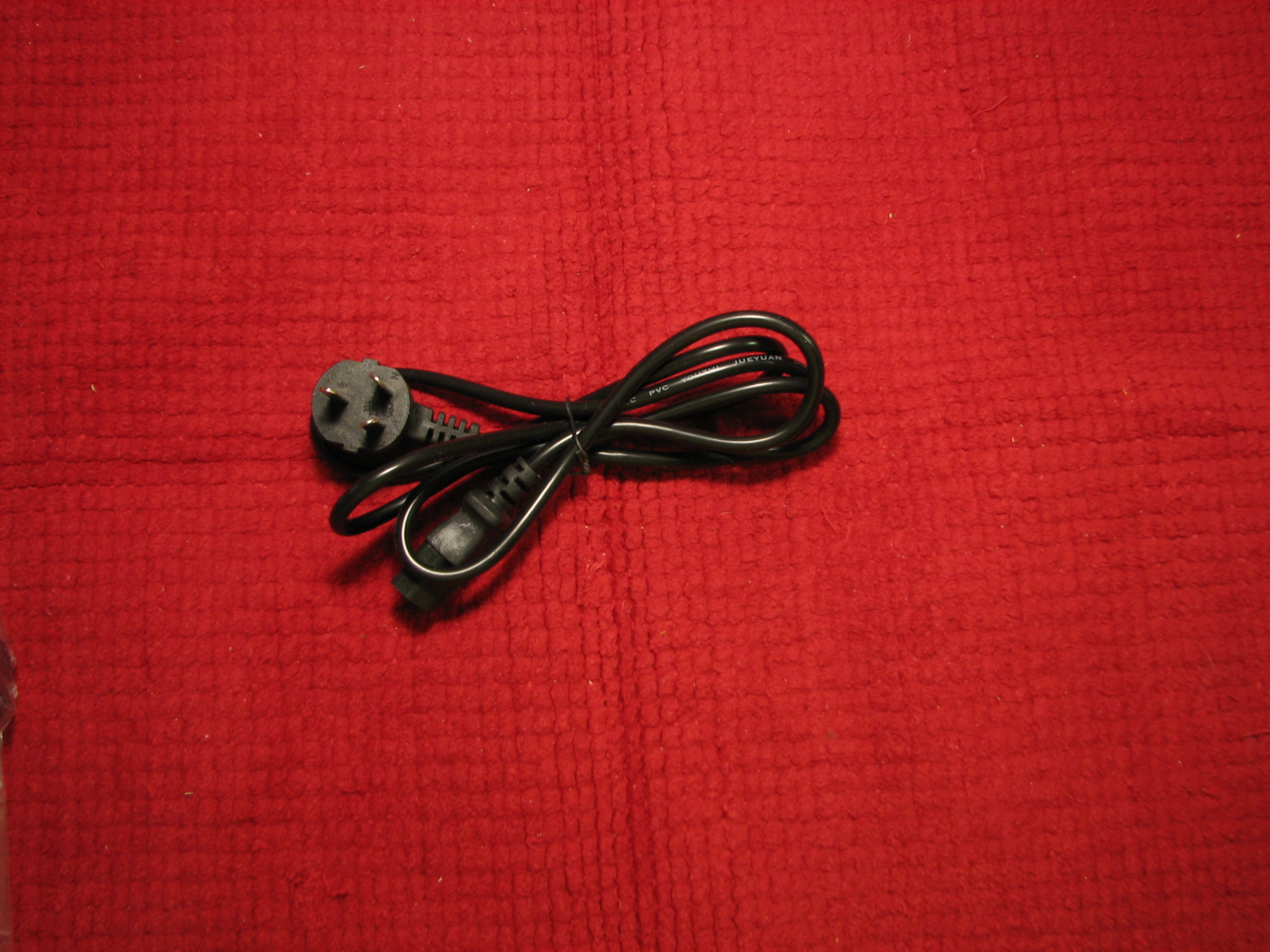
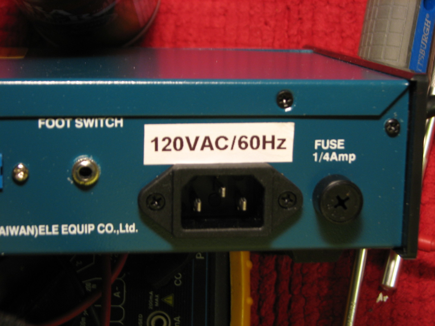
The JND Advanced 983A glue dispenser makes for an excellent surface mount solder paste applicator. Here we will discuss rewiring the transformer for use in the USA at 120VAC/60Hz input voltage. This model comes with an EU style IEC plug that is designed to operate on 220VAC. It is a very simple conversion to 120VAC. Here is what it looks like in and out of the box.
The conversion
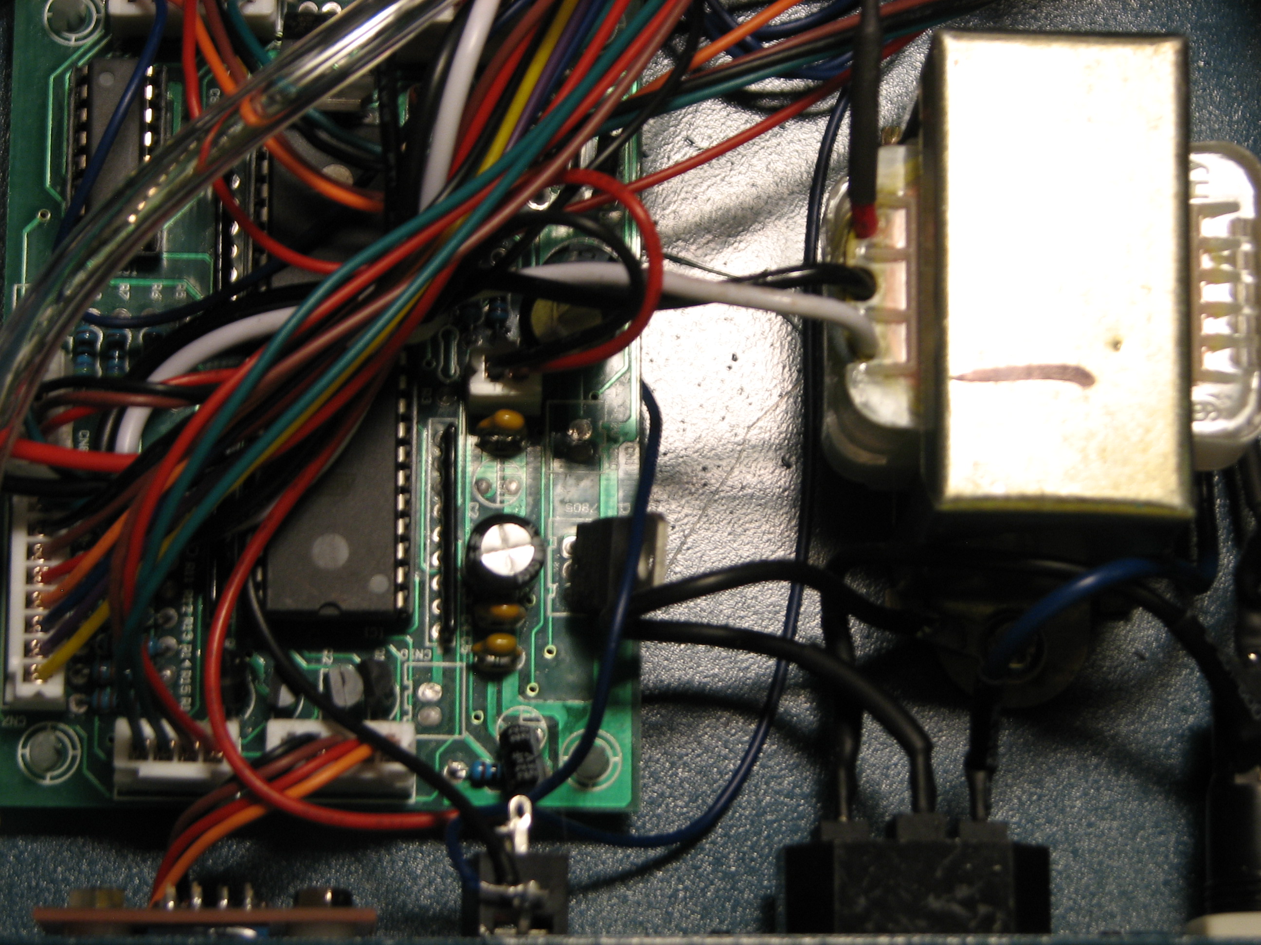
Converting these units to operate on 120VAC as apposed to the 220VAC input they come shipped as is quite easy. Ironically once you disassemble the unit you will notice that the transformer is already made to accommodate either voltage. In fact, mine looked like they were converted to run on 220VAC as one of the ends of the transformer was cut off and had heatshrink tubing over one of the outer wires to keep it from shorting against anything and the board was tied into the center tap of the transformer instead. Start by dissembling the dispenser.
The transformer
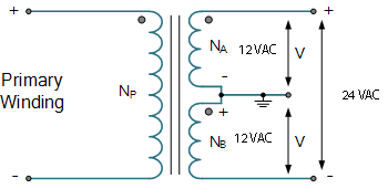
Let’s take a look at an example of an ordinary center tapped transformer. As you can see from the illustration the device requires 12VAC to operate which is accomplished by connecting from NA or NB leg of the transformer and the center tap. Our primary winding is what plugs into your wall outlet. While it was wired to expect 220VAC, we will be halving that and inputting 120VAC. If you look at this example and compare it to our dispenser transformer, it becomes very clear how to rewire the transformer to output the proper secondary voltage with a primary winding with our lower input. Notice that between both NA and NB and the center tap, we see a potential of 12VAC as opposed to the full secondary winding which outputs twice that across it at 24VAC. We are going to half the primary voltage to 120VAC from 220VAC. So, in order for the secondary to output the same voltage, we need to use the entire secondary to double the output voltage. Halving the primary winding input mandates doubling the secondary output to produce the same secondary output.
Getting down to business
You will need a pair of wire cutters, a soldering iron, solder (preferably, rosin core 63/37 [eutectic] electrical solder) I use Kester solder mostly, but there are other manufacturers out there that make quality solder. NOTE: I do not recommend silver solder due to its higher melt and remelt temperatures… You should use rubber gloves to protect your hands from absorbing the lead from the solder. You will also need a couple of pieces of appropriately sized heatshrink tubing to make a safe and neat job of the conversion. Also a heatgun or hair dryer to shrink the heatshrink tubing. So now that we are ready and have a clear area to work, let’s get started.
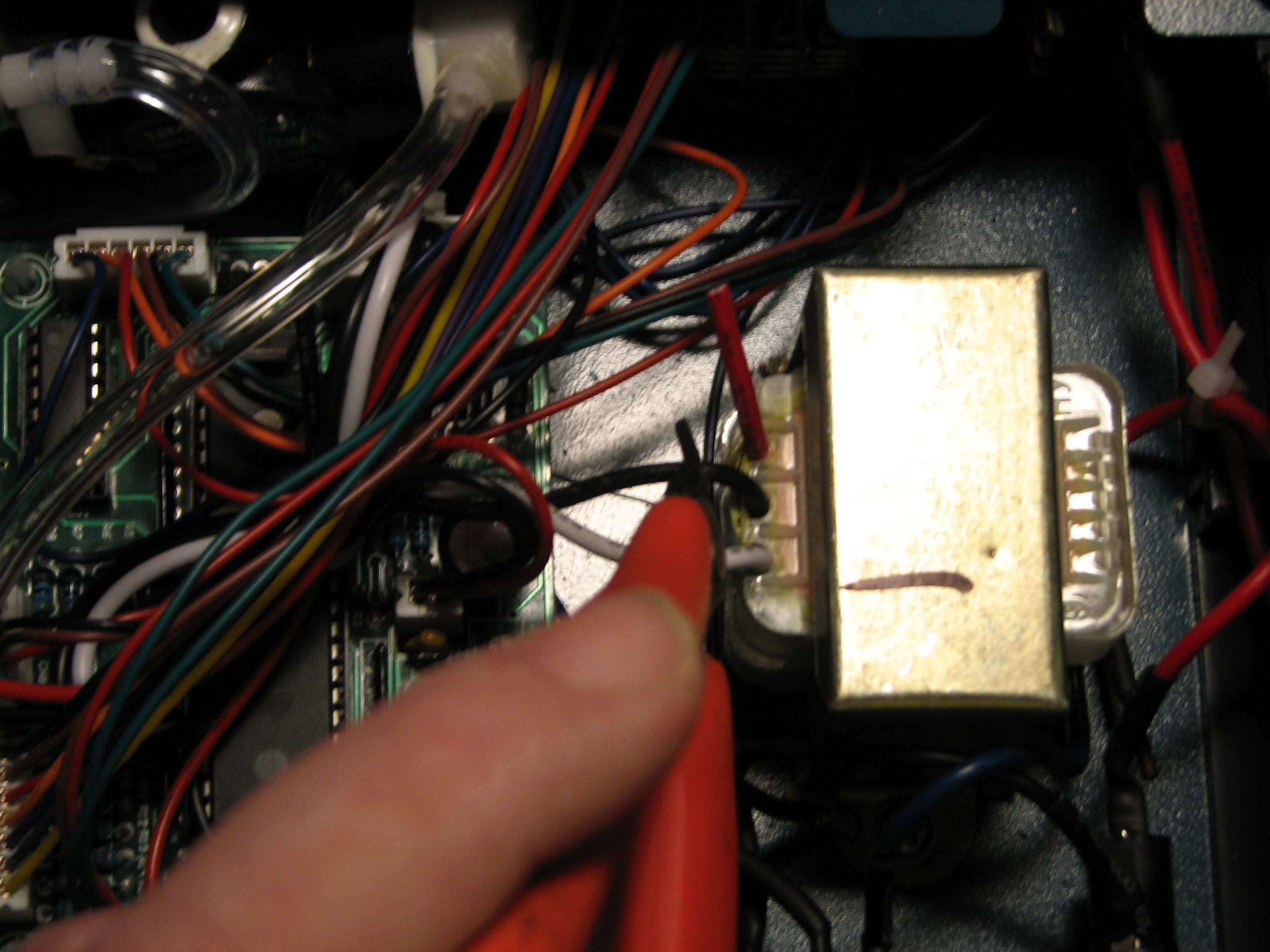
Start by cutting the secondary’s center tap wire – the black one in the center of the transformer in the image below. Make sure you leave enough wire from the board for the wire to connect to the red outside secondary wire (I removed the black heatshrink tubing from it.)
Preparing for soldering
Now we need to strip and prepare the secondary wire for soldering to the black wire coming from the board. Now prep the black wire you cut that is attached to the PC board to be soldered to the end red secondary wire. Cut two adequate lengths of the properly sized heatshrink tubing and place one on the cut off secondary center tap wire on the transformer and shrink it down to keep the end from possibly contacting anything. Next we need to remember to push a piece of heatshrink tubing on the black wire to the PC board up toward the board in order for the heat from soldering does not shrink the tubing while we are soldering. Now solder the black wire from the board to the outside secondary (red) wire and then push the heatshrink tubing over the solder connection of the wires and shrink it over the bare wires you just soldered.
Finishing up
Once the transformer wiring modification is complete, you can use some zip ties to organize the wiring some and keep it off of other components; the dispenser should have had one or two in place when you dissembled it. Now reassemble the case. The last component you need to acquire is a common IEC 120VAC power cable – just like is common to say a computer power cable. Also it is a good idea to relabel the unit indicating it is now wired for USA 120VAC/60Hz over the 220VAC labeling.
Finally, plug in the 120VAC IEC cable to the back of the unit, plug the other end into your wall outlet and test for functionality. Now you are ready to start working on all of your surface mount electronic projects! Incidentally, Amazon is now carrying these units and they are published as running on 120VAC. When mine were purchased, these were only available from over seas and were set up for 220VAC. I can say the units I purchased abroad were quite a bit less expensive than Amazon’s offering.
Happy re-flowing!

