The amplifier
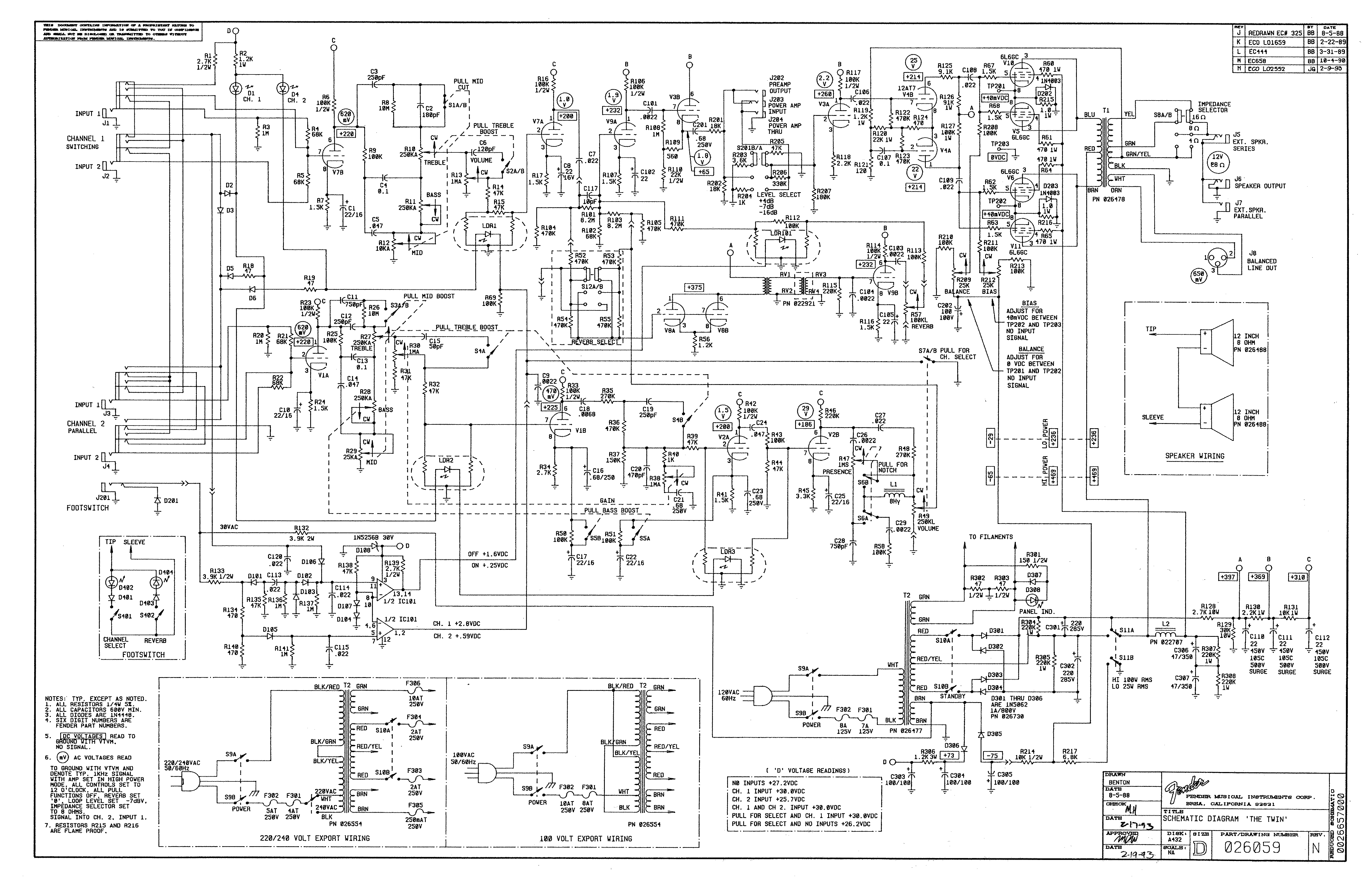
As a new owner of a Fender Dual Showman red knob reverb amplifier head, I set out to get a footswitch for my prize. The Fender “The Twin” of that period was almost exactly the same as the Dual Showman head (only MUCH heavier with its compliment of speakers.) After talking to about 20 sources including Fender and exhaustive searches on the Internet, I had gotten a handful of answers, but most were different; mostly debate about whether it called for a one or two switch foot-pedal or not. If you try looking it up, much of the data indicates the amp should have a single switch footswitch to just control the channels. There were not many made in this era that had reverb, but I happened to own one. So after getting nowhere asking around, I grabbed the schematics from a Fender “The Twin” amp and what I found did not surprise me in the least.
The problem
If you have a modern red knob Dual Showman, it could have been outfitted with either a damping selector or reverb. The reverb units were pretty low volume amps; that’s why we don’t see as many in the used market. From a cursory look at the schematics, I could tell first that any red knob unit not equipped with the damping option was going to have a two switch footswitch assignment. So, knowing the Dual Showman circuits and “The Twin” amp circuits were essentially identical, I homed in on the control circuit for the switch and finally decided on what switch to order.
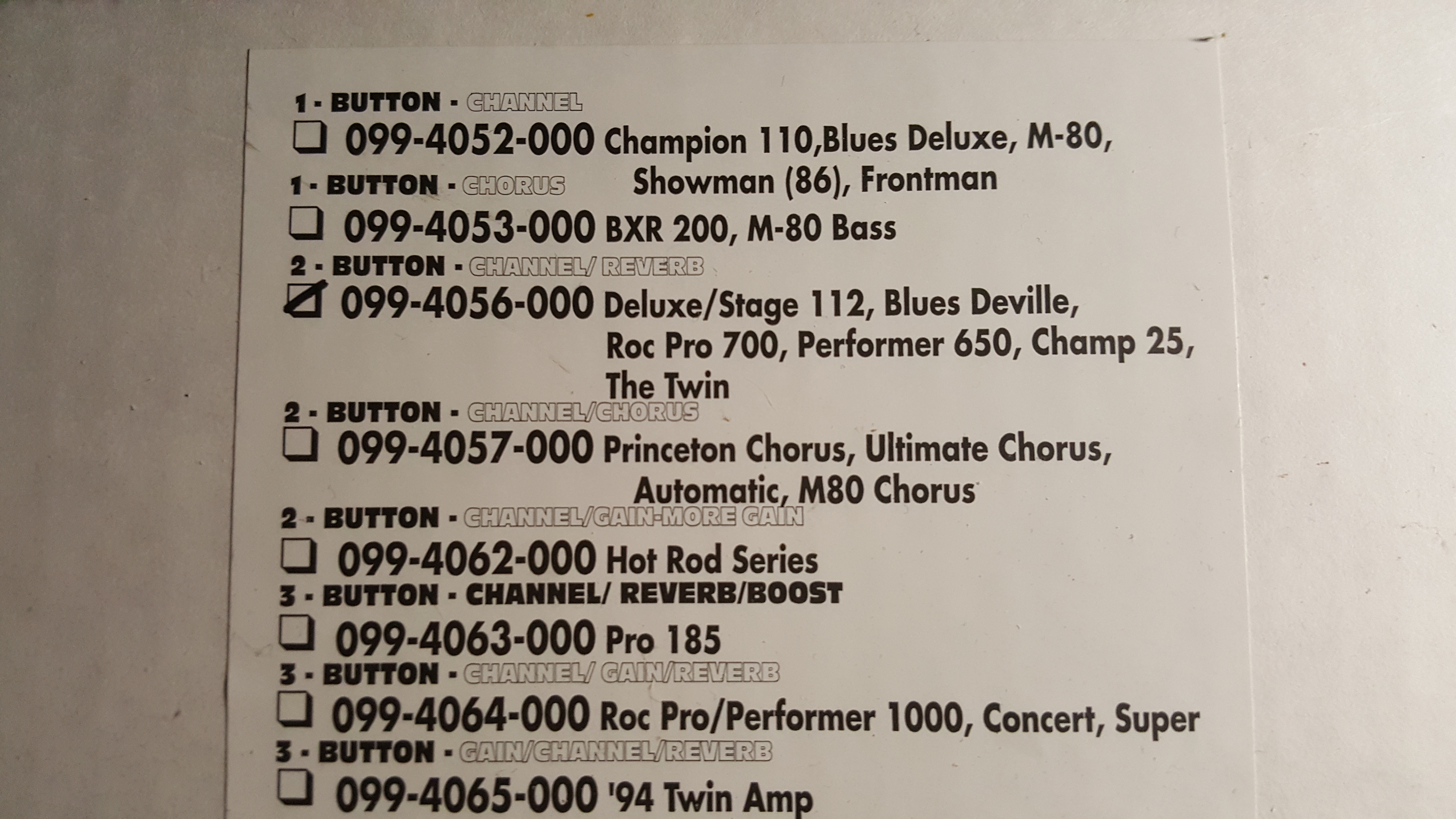
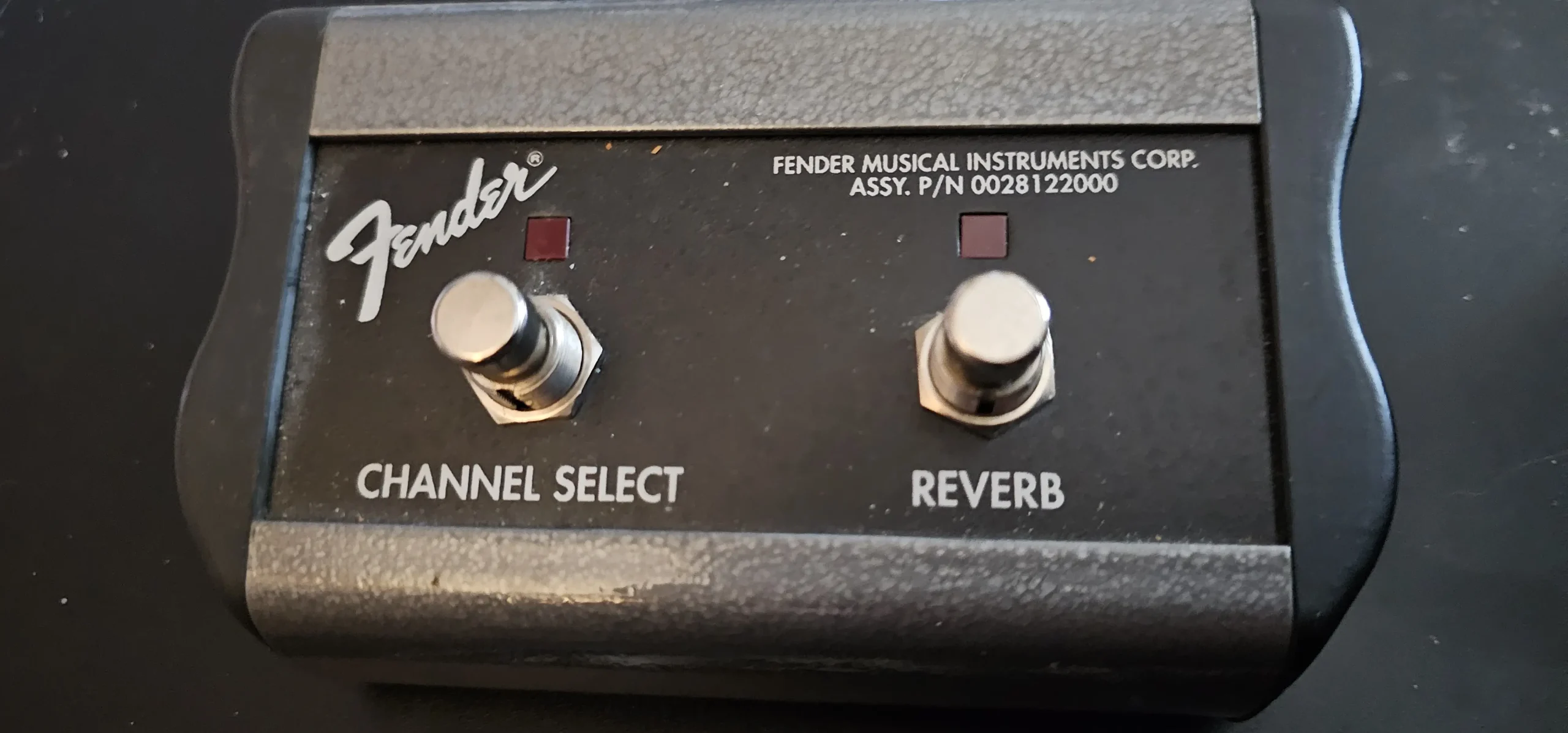
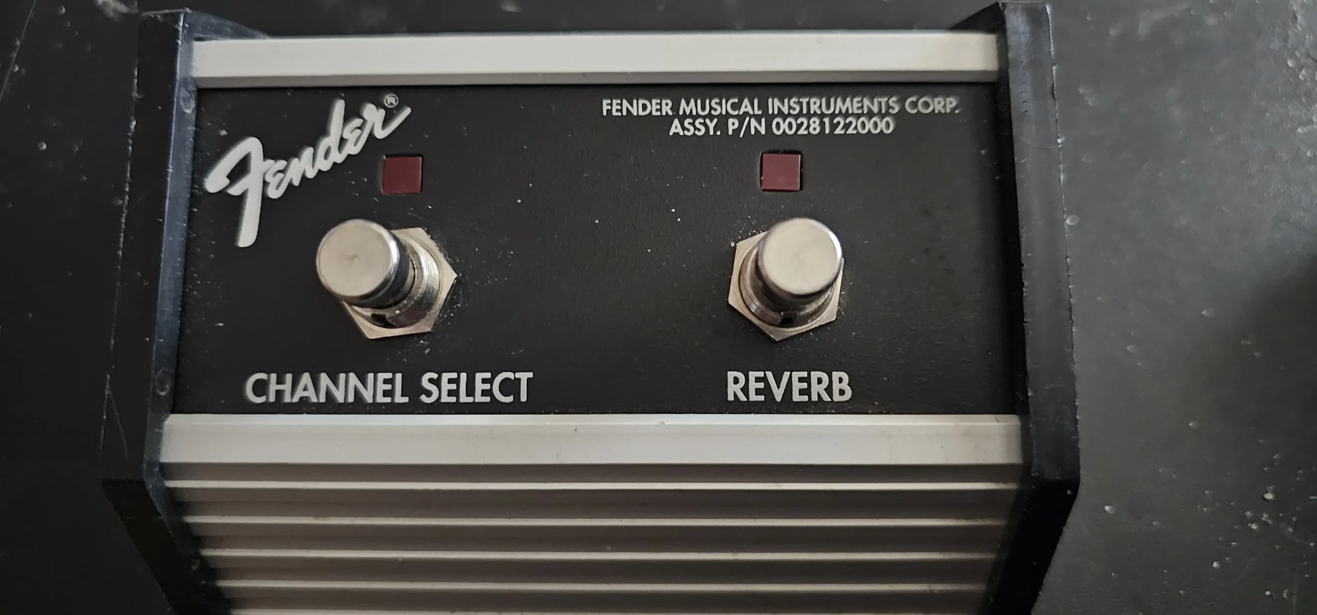
As you can see from the box, (and the part number labeled on the switch) this looks like it is going to be plug and play. So after unwrapping the footswitch (which are now not made like the originals, style-wise) I plugged it in and went a stomping. Something was amiss. The left switch marked “Channel” was actually controlling the reverb and the switch on the right was controlling the channel. Crap! So back to the schematic.
I knew from prior work on this era of Fender amps that the footswitches only used two wires and used diodes to change the DC that was plugged into the footswitch. Sure enough inside was really simple with some diodes, LED’s and such so all that would need to be done is to reverse all of the diodes in the footswitch. Don’t forget an LED is a diode…
My switch called for some pretty high-brow diodes (IN4448) in the circuit and I did not have any laying about. They had done quite a nice job of soldering everything together and I suspected I might not be able to reverse the diodes already in place due to how short the leads had been trimmed, but since I had nothing to loose I went ahead and tried. What do you know? I was able to get everything reversed and soldered up properly. Plugged the pedal back in and all was as it should be. The left switch labeled “channel” controlled the channel and the right switch controlled the reverb (on/off) – just as it was meant to be.
The footswitch solution
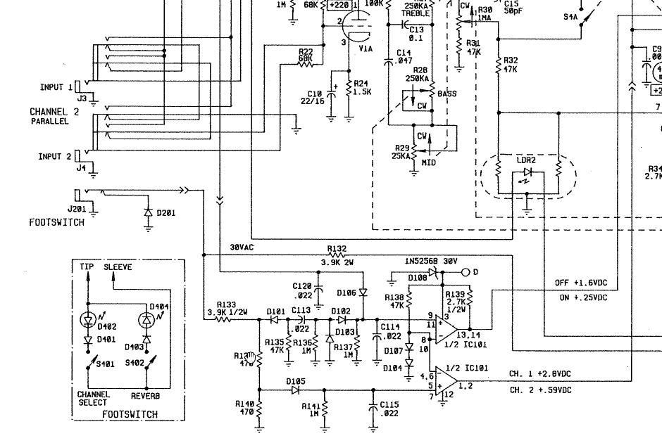
Below I have attached a copy of the full sized red knob Fender “The Twin” schematic as well as a zoomed in shot of the footswitch where it is readily apparent all that needs done is have all of the components’ (less switches) polarity reversed. This should take you about 10 minutes. If you cannot reuse the diodes (you should have no trouble with the special long leaded LED’s…) Fender calls for IN4448 diodes. You can likely get away with lesser more available diodes for the footswitch.
…and here is the business end you will be working with to get the footswitch to behave properly.
Things you will need
- A clean work surface.
- #2 Phillips head screwdriver.
- A 9/16″ nutdriver or socket and ratchet (Don’t over tighten if you must use a ratchet!)
- Quality soldering iron.
- Solder sucker/vacuum or desoldering braid and flux.
- Rosin core 63/37 (eutectic) solder. (Silver solder not recommended here due to high melt temps.)
- Flux cleaning solution to clean the PCB during and after it has been re-worked.
- Two IN4448 diodes if you have them as they are much easier to install with long leads on them.
- Regardless of whether you can reuse the diodes, you pretty much need to reuse the LED’s.
In the footswitch schematic and PCB you will see the diodes’ polarity is marked by their cathode.
Diode Polarity
Likewise, the stock cathode connections should be silk-screened on the PCB. You need to unsolder and remove the two diodes as well as the two LED’s (Light Emitting Diodes). The cathode sides (the end you will see the stripe on the diode) are silk-screened right to the board as well as present on the diodes themselves, so all you need to do is insert them and solder them in with their polarity reversed. The LED’s since the leads have already been cut off, look for a flat side nearest the pins. This will be the cathode (negative) side. This procedure is really simple and more time will be spent disassembling, reassembling cleaning and such of the footswitch than reversing the two diodes and two LED’s. The two LED’s will likely need reused due to their long lead length and unique square emitter design.
A word of caution – do not over tighten the jack, switches or screws on the pedal as you could ruin something, most likely the mono I/O jack as it is made mostly of plastic. Nothing needs to be overly tight and it is best to have to tighten them up some further off in the future than to buy replacement parts to fix the damaged ones. Happy jamming!
Addendum
After combing the used market, I finally found a proper vintage OEM footswitch for the Dual Showman SR Red Knob (or its cousin “The Twin”). Notice it has the same part number stenciled on it, unless something has changed, they are NOT THE SAME INTERNALLY! This vintage switch works properly right out of the box with no modifications unlike the one outlined above. I don’t know why Fender printed the P/N on the new footswitch (order P/N 099-4056-000) the same as the original when it is NOT the same internally. This defies all logic on their part. The new footswitch above that requires modifications to work properly might be what you want if you don’t mind modding it, for it would fit on a pedal board more readily. I don’t use a pedal board with this amp, so I was happy to come across an original switch, as the styling matches my Fender Concert’s footswitch that I am used to using. Again, barring a change, ordering the P/N 099-4056-000 is going to net you a footswitch as detailed above that requires modification. Take a look below at what the original foot switch for the amp looks like. If you can find one in the used market like it, you’ll not need to go through the modification process and it will indeed be plug & play…

